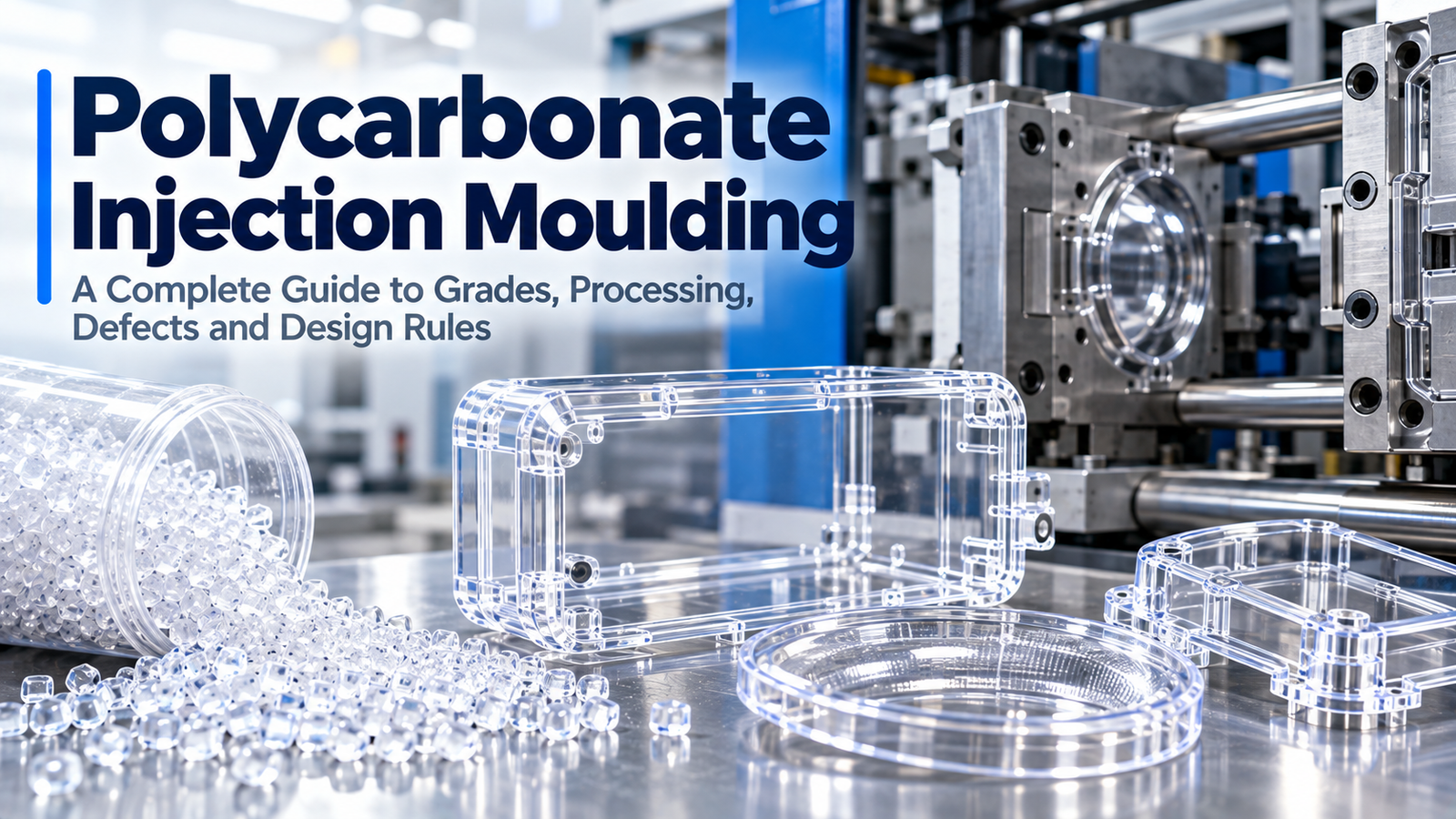
Polycarbonate is the plastic engineers reach for when a part must be transparent, tough and dimensionally stable at the same time. It survives impact that shatters acrylic, holds its shape at temperatures that soften ABS, and can be moulded to optical clarity. It is also one of the least forgiving materials in the injection moulding shop: it absorbs moisture aggressively, degrades quickly when overheated, and locks residual stress into the part that only shows up months later as a crack or a haze.
This guide covers PC injection moulding end to end — grades, drying, the processing window, shrinkage and tolerances, residual stress, defect control, chemical compatibility and design rules.
Why PC Behaves Differently From Other Plastics
| Property | PC behaviour | What it means in practice |
|---|---|---|
| Structure | Amorphous | Fairly uniform shrinkage, good dimensional stability, high clarity |
| Shrinkage | 0.5 to 0.7 percent | Higher than ABS, and sensitive to mould temperature |
| Melt viscosity | High | Needs more pressure and a properly sized gate; shear heating is a real risk |
| Moisture absorption | Around 0.15 percent at 24 hours | Small figure, but PC hydrolyses — it must be dried hard |
| Impact strength | Very high | But strongly reduced by notches, weld lines and residual stress |
| Heat resistance | Moderate to high | Usable around 120 °C, with high heat grades above that |
| Chemical resistance | Poor against many solvents | Stress cracking is a leading cause of field failure |
| Thermal expansion | High | Dimensions move noticeably with temperature; account for it in fits |
The combination of high melt viscosity and moisture sensitivity is what makes PC difficult. It needs to be run hot enough to flow and dry enough not to hydrolyse, and those two requirements punish any shortcut.
PC Grades and When to Use Each
| Grade | Distinguishing feature | Typical application |
|---|---|---|
| General purpose | Balanced optical and mechanical properties | Housings, guards, covers |
| High flow | Lower viscosity for thin walls and long flow paths | Thin-wall enclosures, large panels |
| Flame retardant | UL 94 V-0, usually at the cost of some clarity and impact | Electrical enclosures, chargers |
| UV stabilised | Protection against yellowing and embrittlement | Outdoor lenses, glazing, signage |
| Optical / media grade | Low contamination, high transmission | Lenses, light guides, displays |
| High heat | Higher deflection temperature | Automotive lighting, appliances |
| Glass filled | Higher stiffness and lower creep | Structural brackets, frames |
| PC/ABS blend | Improved processing and lower cost | Laptop and device enclosures |
Grade choice follows the service environment: sunlight demands UV stabilisation, live electrical parts demand V-0, and any part that must stay clear should not be specified in a flame retardant grade unless the clarity loss is acceptable.
Property data should be taken from the supplier's data sheet for the specific grade, because the spread across PC grades — particularly between optical and flame retardant versions — is wide.
Drying PC: The Step That Decides Everything
Polycarbonate must be dried to a low residual moisture level before processing. If it is not, the water hydrolyses the polymer at melt temperature, breaking the molecular chains and permanently reducing impact strength. A wet part may look acceptable and still fail on impact.
| Parameter | Recommendation |
|---|---|
| Drying temperature | 120 °C |
| Drying time | 3 to 4 hours at temperature |
| Dew point | Minus 20 °C or lower |
| Target residual moisture | Below 0.02 percent |
| Dryer type | Desiccant dryer, ideally with a hopper that keeps material dry during running |
| Handling | Never leave dried PC open to the air; it regains moisture within hours |
Signs that the resin was not dried properly:
- Silver streaks and splay on the surface
- Bubbles or voids in thick sections
- Reduced impact strength and brittle failure, without any visible defect
- Inconsistent clarity in transparent parts
- A drop in melt viscosity that looks like "good flow" but is actually chain scission
The last two are the dangerous ones, because hydrolysis can reduce performance without producing an obvious cosmetic defect. Where degradation from overheating is suspected instead of moisture, the visual signature is different — our note on avoiding PC degradation from shear overheating explains how to tell the two apart.
Processing Window for Polycarbonate
| Parameter | Typical range | Note |
|---|---|---|
| Melt temperature | 280 to 320 °C | Higher for high flow and optical grades; keep within the supplier's window to avoid hydrolysis and yellowing |
| Mould temperature | 80 to 120 °C | Higher mould temperature reduces stress and improves clarity and weld strength |
| Injection speed | Moderate to fast, profiled | Fast enough to avoid freeze-off, slow enough to avoid shear degradation at the gate |
| Holding pressure | 40 to 60 percent of injection pressure | Excessive hold builds residual stress |
| Back pressure | Low, 3 to 10 bar | High back pressure adds shear heating with no benefit |
| Screw speed | Low to moderate | PC is shear sensitive; keep screw speed down and rely on melt temperature |
| Residence time | Keep short | Long residence time at high temperature causes yellowing and degradation |
| Regrind | Limit and dry again | Degraded material should not be reused |
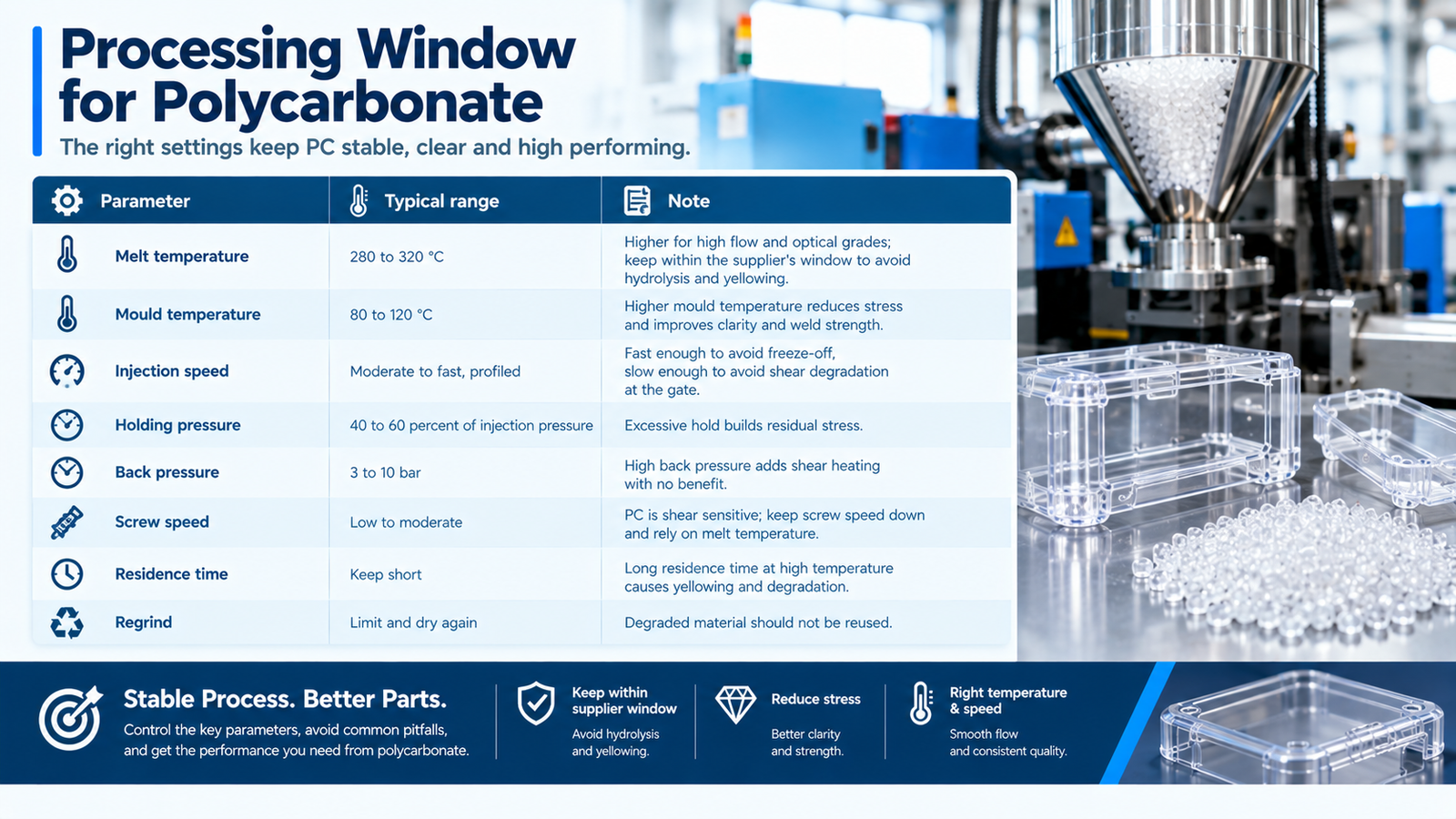
Two rules matter more than the rest. First, melt temperature must be verified with an air shot, not read off the controller. Second, mould temperature is the main lever for residual stress, clarity and weld line strength — running a cold tool to shorten the cycle is the most common cause of stress cracking in service.
Shrinkage, Tolerances and Dimensional Control
| Grade | Typical shrinkage |
|---|---|
| General purpose | 0.5 to 0.7 percent |
| High flow | 0.5 to 0.7 percent |
| Flame retardant | 0.5 to 0.7 percent |
| Glass filled 10 to 30 percent | 0.1 to 0.4 percent, with strong directional difference |
| PC/ABS blend | 0.4 to 0.6 percent |
Achievable tolerances for a well-designed PC part are plus or minus 0.05 mm on general dimensions, with plus or minus 0.02 mm on critical features when the process is stable and measurement is done on an appropriate instrument. Shrinkage in PC is sensitive to mould temperature and wall thickness, so a tool designed from generic data will drift; the shrinkage figure must come from the actual grade with the intended mould temperature.
Because thermal expansion is high, parts that operate over a wide temperature range need their fits and clearances calculated at both extremes, not at room temperature alone.
Residual Stress: The Root Cause of Most PC Failures
Residual stress is frozen into the part when the melt is packed against a cold tool and the skin solidifies before the core. It reduces impact strength, promotes warpage and makes the part far more susceptible to chemical attack.
Where stress is a concern, annealing relieves it:
| Section thickness | Typical annealing time at 120 to 125 °C |
|---|---|
| Up to 2 mm | 1 hour |
| 2 to 4 mm | 2 hours |
| 4 to 6 mm | 3 hours |
| Over 6 mm | 4 hours or more |
Annealing must be followed by slow cooling — typically a controlled ramp down over several hours. Quenching an annealed part builds a new stress pattern and can be worse than doing nothing. For optical parts, the relationship between internal stress and clarity is well documented; our guide to reducing internal stress in polycarbonate lenses covers the optical side of the same problem.
Common PC Defects and How to Fix Them
| Defect | Likely cause | Fix |
|---|---|---|
| Silver streaks | Wet resin or decomposition | Dry to below 0.02 percent, check melt temperature and residence time |
| Yellowing or black specks | Overheating, long residence time, dead spots in the barrel | Reduce melt temperature, purge the barrel, check screw and non-return valve |
| Flow marks and dull patches | Cold mould, slow fill, low melt temperature | Raise mould temperature, increase injection speed, review the gate |
| Weld lines with poor strength | Low mould temperature, poor venting, gate position | Raise mould temperature, add venting at the weld, reposition the gate |
| Warpage | Uneven cooling or packing, gate imbalance | Balance cooling circuits, review gate location and hold profile |
| Stress cracking in service | Moulded-in stress plus chemical contact | Reduce packing stress, anneal the part, change the cleaning agent or the assembly method |
| Sink marks | Thick sections, short hold | Reduce wall thickness, extend hold, core the boss |
| Jetting at the gate | Gate too small, fill too fast at entry | Enlarge the gate, slow the initial fill, adjust the gate angle |
| Haze or reduced clarity | Moisture, contamination, or high residual stress | Dry properly, keep the barrel clean, raise mould temperature, anneal |
Most of these resolve into three families: moisture, heat history and stress. If you are working through a defect systematically, our guide to solving common defects in polycarbonate injection moulding parts follows the same symptom-to-cause logic.
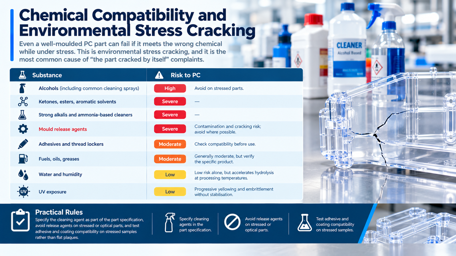
Chemical Compatibility and Environmental Stress Cracking
Even a well-moulded PC part can fail if it meets the wrong chemical while under stress. This is environmental stress cracking, and it is the most common cause of "the part cracked by itself" complaints.
| Substance | Risk to PC |
|---|---|
| Alcohols (including common cleaning sprays) | High — avoid on stressed parts |
| Ketones, esters, aromatic solvents | Severe |
| Strong alkalis and ammonia-based cleaners | Severe |
| Mould release agents | Contamination and cracking risk; avoid where possible |
| Adhesives and thread lockers | Check compatibility before use |
| Fuels, oils, greases | Generally moderate, but verify the specific product |
| Water and humidity | Low risk alone, but accelerates hydrolysis at processing temperatures |
| UV exposure | Progressive yellowing and embrittlement without stabilisation |
Practical rules: specify the cleaning agent as part of the part specification, avoid release agents on stressed or optical parts, and test adhesive and coating compatibility on stressed samples rather than flat plaques. Where cracking has already appeared, our guide to preventing cracking in high-stress polycarbonate parts works through the diagnosis.
Design Guidelines for PC Parts
| Feature | Recommendation |
|---|---|
| Nominal wall | 2 to 3.5 mm typical; keep thickness as uniform as possible |
| Inside radii | At least half the wall thickness; PC is notch sensitive, so sharp corners are unacceptable |
| Outside radii | Match the inside radius plus wall thickness |
| Draft | 0.5 to 1 degree minimum, more on textured surfaces |
| Ribs | Around 60 percent of nominal wall to avoid sink and stress |
| Bosses | Wall around 60 percent of nominal wall, cored, with generous radii at the base |
| Gates | Large enough to avoid shear degradation; hide the gate on a non-critical face |
| Venting | 0.02 to 0.03 mm at the last point to fill, and at weld line locations |
| Inserts and threads | Avoid sharp notches; use generous radii or metal inserts for high-load joints |
The design stage is where PC parts are won or lost. Wall uniformity, radii and gate position determine whether the part can be moulded with low stress — and low stress is what makes the difference between a part that lasts for years and one that cracks in service. For thin-wall applications the constraints are tighter still, as discussed in our guide to lightweight PC thin-wall moulding for laptop housings.
Secondary Operations With PC
- Annealing relieves stress and stabilises dimensions; always with a controlled cooling ramp.
- Painting, printing and coating work well, but solvent-based inks and coatings can attack stressed PC. Test on stressed samples.
- Hard coating for scratch resistance has real technological limits — the coating system must match the substrate, and coating stress is a common cause of crazing.
- Laser cutting, machining and drilling are all possible, but sharp tooling and slow feeds are essential to avoid local cracking.
- Ultrasonic welding works well; the joint design decides the strength.
- UV protection must be built into the grade or applied as a coating for any outdoor part.
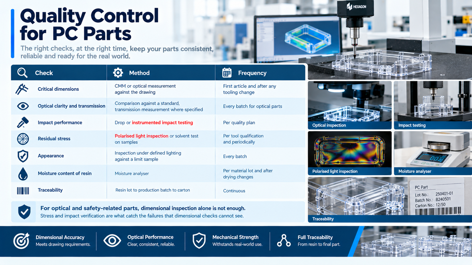
Quality Control for PC Parts
| Check | Method | Frequency |
|---|---|---|
| Critical dimensions | CMM or optical measurement against the drawing | First article and after any tooling change |
| Optical clarity and transmission | Comparison against a standard, transmission measurement where specified | Every batch for optical parts |
| Impact performance | Drop or instrumented impact testing | Per quality plan |
| Residual stress | Polarised light inspection or solvent test on samples | Per tool qualification and periodically |
| Appearance | Inspection under defined lighting against a limit sample | Every batch |
| Moisture content of resin | Moisture analyser | Per material lot and after drying changes |
| Traceability | Resin lot to production batch to carton | Continuous |
For optical and safety-related parts, dimensional inspection alone is not enough. Stress and impact verification are what catch the failures that dimensional checks cannot see.
Conclusion
PC injection moulding rewards a disciplined process and punishes shortcuts. The resin must be dried to below 0.02 percent moisture, the melt temperature verified with an air shot, the mould run hot enough to keep residual stress low, and the design made tolerant of a notch-sensitive material. Get those right and polycarbonate delivers a combination of clarity, toughness and heat resistance that no other common plastic matches. Get them wrong and the failures appear as silver streaks at the press, or as stress cracks months later in the field.
The most expensive PC problems are the ones designed into the part before the tool is cut. Early communication between the customer and the moulder — on service conditions, chemical contact, tolerances and appearance — costs nothing and prevents most of them.
With injection moulding capability from 80 to 1,400 tonnes and in-house tooling, we run polycarbonate across general purpose, high flow, flame retardant, UV stabilised, optical, high heat and glass-filled grades. Through our custom injection moulding services we support PC projects from design review and material selection through first article inspection to stable volume production. Send us your part drawing and service conditions to discuss grades, tolerances and the process window for your application.
FAQ
What is PC injection moulding?
PC injection moulding is the production of parts from polycarbonate, a tough transparent engineering thermoplastic. It is used for lenses, light guides, guards, medical housings and impact-resistant enclosures, and it requires careful drying and a hot mould to achieve clarity, strength and low residual stress.
Does polycarbonate need to be dried before moulding?
Yes, and more strictly than most materials. PC should be dried at about 120 °C for 3 to 4 hours with a dew point below minus 20 °C, targeting a residual moisture content below 0.02 percent. Wet PC hydrolyses at melt temperature, which permanently reduces impact strength even when the part looks acceptable.
What is the best mould temperature for polycarbonate?
Between 80 and 120 °C, with higher temperatures giving lower residual stress, better clarity and stronger weld lines. A cold tool shortens the cycle but builds stress into the part and is the most common root cause of stress cracking in service.
Why do polycarbonate parts crack after assembly?
Usually a combination of moulded-in residual stress and chemical exposure, known as environmental stress cracking. Alcohol-based cleaners, solvents, alkalis, adhesives and release agents are common triggers. Reducing packing stress, annealing the part and changing the cleaning agent usually solves it.
What is the shrinkage rate of polycarbonate?
General purpose PC shrinks about 0.5 to 0.7 percent. Glass-filled grades shrink less, from around 0.1 to 0.4 percent, but with a much greater difference between flow and cross-flow directions. Shrinkage is sensitive to mould temperature, so the tooling data must come from the actual grade and the intended process conditions.
Can polycarbonate be annealed?
Yes. Annealing at 120 to 125 °C for one hour per 2 mm of section thickness relieves moulded-in stress, followed by slow controlled cooling. Annealing improves dimensional stability and reduces the risk of stress cracking, and it is common practice for optical and highly stressed parts.